

Comparing DIP, SMD, and FlipChip LED Technologies

-
Author President
-
Published February 03
2025
Dual Inline Package (DIP) was the original LED technology used primarily for outdoor LED billboard displays. Pixel pitches of P18 were standard as viewers were far from the LED displays themselves. DIP consists of 3 individual LED chips—1 red, 1 green, and 1 blue—that are soldered manually to the PCB board. DIP LED displays are used today exclusively for outdoor applications with pixel pitches above 10, as DIP chips are too large to allow for pixel pitches below 10.
DIP LEDs are brighter than Surface Mounted Devices (SMD) LEDs and can range from 4500cd/sq. m. to 12,000 cd/sq. m. However, as DIP lamps are soldered to a PCB by hand, they are not as reliable or stable as SMD and are more prone to failure. DIP lamps lose 15% of their brightness after 2000 hours and 20% after 3500 hours.
SMD – Surface Mounted Devices has enabled much smaller pixel pitches, ranging from P10 to P1, due to the smaller chips used. These smaller bulbs, relative to DIP chips, allow for more LEDs in the same area.
The SMD process encapsulates 1 red, 1 green, and 1 blue chip into a small bulb/lamp, which is then mechanically soldered directly to the PCB board in a 4-step process. Aside from a lower brightness level—less critical for indoor LED video applications—SMD is far superior to DIP.
The viewing angle of SMD is 140-160° (horizontal and vertical), whereas DIP is 100° horizontal and 50° vertical.
SMD screens have lower brightness than DIP: Indoor – 800-1200 nits, Outdoor – 4500-6000 nits.
SMD screens support closer viewing distances due to smaller pixel pitches.
SMD chips are 30% more efficient than DIP, reducing electricity costs.
SMD lamps generate less heat.
SMD lamps use fewer raw materials than DIP, making SMD screens lighter.
SMD lamps can last up to 100,000 hours, with failure rates estimated at 50-100 PPM versus DIP at 100-200 PPM.
SMD uses a 4-step manufacturing process.
The SMD structure has many welding points, leading to theoretically more failure points than Micro LED or Chip on Board (COB) technology.
If Glue-On-Board epoxy resin is used, a perfectly flat surface cannot be achieved, whereas Micro LED allows for a completely flat surface.

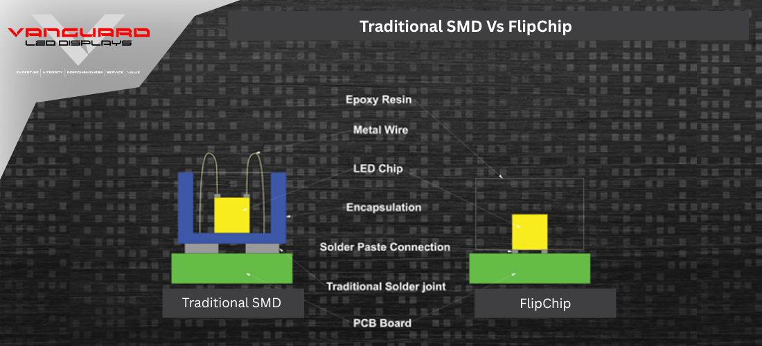
SMD – Surface Mounted Devices – FlipChip
“FLIPCHIP” is a revolutionary technology for encapsulating fine pixel pitch SMD 1010 LED lamps onto PCB boards. Traditionally, SMD circuit design has the Positive pole (Anode) and Negative pole (Cathode) facing upwards. However, in the “FLIPCHIP” process, both electrodes face downward, enabling a unique encapsulation method.
There is no soldering in the “FLIPCHIP” process! The chip and substrate are electrically and mechanically interconnected by solder paste bonding. The solder used in the “FLIPCHIP” process is 100 times stronger than that used in the standard SMD process. Vanguard guarantees a failure rate of 5 PPM in year 1, 20 PPM in year 2, and 15 PPM in year 3, compared to SMD displays, which have a failure rate of 50-100 PPM in year 1.
The “FlipChip” process also employs Common Cathode technology, where electric current passes through the Cathode (negative pole/ground). Power is only drawn as needed, significantly reducing heat generation.
Recent Post
Featured Post

Mastering the Art of Outdoor LED Displays: A Comprehensive Guide
REACH OUT TO US
Fill out the form below, and lets get started!
Please Note: To ensure legitimate corporate inquiries, only business email addresses are accepted. Submissions from consumer email providers (e.g., Gmail, Yahoo, Hotmail, Ymail) will not move forward.
Demo Title
This will close in 50 seconds